
A self-driving car comprises a lot of sensors through which, a tremendous amount of data is collected and monitored to inspect its behavior. One such sensor that plays a significant role in providing vehicle data is the IMU. IMU or Inertial Measurement Unit (IMU) is used in a vehicle to measure its dynamic entities such as longitudinal acceleration, lateral acceleration, pitch angle, yaw angle, etc. One of the use cases I can immediately think of is in case of an accident. If the vehicle rolls over, IMU can trigger an event in which an emergency vehicle can be called directly to the location. Apart from that, the inertial measurements from IMU can also be used to predict the vehicle’s coordinates in cases where the GNSS signals are weak, for instance, in a tunnel.
In this blog, we won’t be rolling over an entire vehicle and we will not be using an actual IMU to gather the gyroscopic. We would rather have a gyro-accelerometer module, MPU-6050, that can be used instead of an actual IMU with Raspberry Pi. These are the two pieces of hardware that we will need in this exercise (along with pin wires of course!). By understanding how to read data from the MPU-6050 using Python on a Raspberry Pi, you’ll unlock the potential to create innovative projects in areas like robotics, drone stabilization, virtual reality, and more. By the end of this blog, you’ll be able to read sensor data as shown in the video below.
[Note: While IMU and gyro-accelerometer sensors have similarities, their names cannot be used interchangeably, as IMU has more functionality and is used in practical cases. Because we are just interested in the angular and accelerational values, GPU-6050 is sufficient and we do not need an actual IMU].
Table of Contents
Brief Introduction to MPU6050
The MPU-6050, often called the “gyro and accelerometer sensor module,” is a small yet compelling electronic component that has found its way into numerous cutting-edge applications. The MPU-6050 is a 6-DOF (Degrees of Freedom) motion-tracking device that combines a 3-axis gyroscope and a 3-axis accelerometer into a single compact module. The sensor is used for measuring motion-related and dynamic entities like acceleration, velocity, orientation, displacement, etc. of a system or an object.

An MPU-6050 operates based on micro-electromechanical systems (MEMS) technology. The gyroscope measures angular velocity, allowing it to detect rotational movements, while the accelerometer measures acceleration in three axes, enabling the module to sense linear movements and changes in orientation. By combining data from both sensors, the MPU-6050 can provide accurate and real-time information about an object’s motion and orientation. This data is then processed by the module’s onboard digital signal processor, making it a valuable tool for applications like robotics, drones, and gesture recognition, among others.
Schematic Diagram of the MPU-6050 sensor module
The sensor module as seen in the figure below consists of 8 pins:

- VCC: This pin is the connection to power the module.
- GND: This pin connects to the ground pin on your Arduino/RasPi.
- SCL: SCL stands for Serial Clock and it provides clock pulse for I2C communication.
- SDA: This pin is used for Serial Data transfer via I2C communication.
- XDA: Auxiliary Serial Data pin and can be used to interface other I2C modules with this sensor module.
- XCL: Like XDA, XCL interfaces Auxiliary Serial Clock with other I2C modules with the sensor module.
- ADD/ADO: This address select pin is useful in case of multiple MPU-6050.
- INT: This is the interrupt pin to indicate that data is available for MCU to read.
Before we begin with the programming part, it is important to understand the coordinates of the sensor.
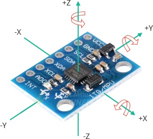
When you read the data, it is crucial to consider the sensor coordinates otherwise it could lead to false data processing. For example, if you place the sensor flat, the acceleration on the Z-axis will show approximately 10 m/s2 (gravitational acceleration). However, if you place it vertically, the same value will then be displayed on the Y-axis. This information comes in handy while working on sensor fusion in the development of autonomous driving where you need to fuse data from multiple sensors.
Let us now start with the programming part.
Source Code
We will start by connecting the sensor to our Raspberry Pi as shown in the figure below.
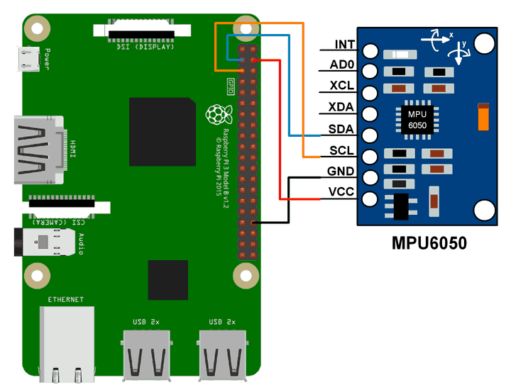
After the wires are connected to the GPIO pins, we need to know the address of our sensor. Run the following code for that:
i2cdetect -y 1If you’ve connected the wires properly, you’ll see the number 68 show up after you run the command. This is in fact a hexadecimal number and tells us the address of the sensor via which the RasPi can communicate. Note the address as it will be useful in our code.
Next, we will look at the code to gain the data from the sensor.
#!/usr/bin/python
import smbus
import math
import os

# Register
power_mgmt_1 = 0x6b
power_mgmt_2 = 0x6c

def read_byte(reg):
    return bus.read_byte_data(address, reg)

def read_word(reg):
    h = bus.read_byte_data(address, reg)
    l = bus.read_byte_data(address, reg+1)
    value = (h << 8) + l
    return value

def read_word_2c(reg):
    val = read_word(reg)
    if (val >= 0x8000):
        return -((65535 - val) + 1)
    else:
        return val

def dist(a,b):
    return math.sqrt((a*a)+(b*b))

def get_y_rotation(x,y,z):
    radians = math.atan2(x, dist(y,z))
    return -math.degrees(radians)

def get_x_rotation(x,y,z):
    radians = math.atan2(y, dist(x,z))
    return math.degrees(radians)

bus = smbus.SMBus(1)
address = 0x68       # via i2cdetect

# Start the bus to send request for data.
bus.write_byte_data(address, power_mgmt_1, 0)

while True:
        print("Gyroscope")
        print("--------")

        gyroscope_x = read_word_2c(0x43)
        gyroscope_y = read_word_2c(0x45)
        gyroscope_z = read_word_2c(0x47)

        print("gyroscope_x: ", ("%5d" % gyroscope_x), " scaled: ", (gyroscope_x / 131))
        print("gyroscope_y: ", ("%5d" % gyroscope_y), " scaled: ", (gyroscope_y / 131))
        print("gyroscope_z: ", ("%5d" % gyroscope_z), " scaled: ", (gyroscope_z / 131))

        print("Acceleratometer")
        print("---------------------")

        acceleration_x = read_word_2c(0x3b)
        acceleration_y = read_word_2c(0x3d)
        acceleration_z = read_word_2c(0x3f)

        acceleration_x_scaled = acceleration_x / 16384.0
        acceleration_y_scaled = acceleration_y / 16384.0
        acceleration_z_scaled = acceleration_z / 16384.0

        print("acceleration_x: ", ("%6d" % acceleration_x), " scaled: ", acceleration_x_scaled)
        print("acceleration_y: ", ("%6d" % acceleration_y), " scaled: ", acceleration_y_scaled)
        print("acceleration_z: ", ("%6d" % acceleration_z), " scaled: ", acceleration_z_scaled)

        print("X Rotation: " , get_x_rotation(acceleration_x_scaled, acceleration_y_scaled, acceleration_z_scaled))
        print("Y Rotation: " , get_y_rotation(acceleration_x_scaled, acceleration_y_scaled, acceleration_z_scaled))
        print("\n\n")
        os.system('cls' if os.name == 'nt' else 'clear')
Let us break it down and go through the steps.
1. Importing the libraries
import smbus
import math
import ossmbus: This library allows communication with I2C devices.math: This library is used for mathematical calculations.os: This library is used for system-related functions.
2. Defining power management
# Register
power_mgmt_1 = 0x6b
power_mgmt_2 = 0x6c
Define two constants, power_mgmt_1 and power_mgmt_2, which are the addresses of registers for power management.
3. Define several functions for reading data from the sensor
def read_byte(reg):
    return bus.read_byte_data(address, reg)

def read_word(reg):
    h = bus.read_byte_data(address, reg)
    l = bus.read_byte_data(address, reg+1)
    value = (h << 8) + l
    return value

def read_word_2c(reg):
    val = read_word(reg)
    if (val >= 0x8000):
        return -((65535 - val) + 1)
    else:
        return val

def dist(a,b):
    return math.sqrt((a*a)+(b*b))

def get_y_rotation(x,y,z):
    radians = math.atan2(x, dist(y,z))
    return -math.degrees(radians)

def get_x_rotation(x,y,z):
    radians = math.atan2(y, dist(x,z))
return math.degrees(radians)read_byte(reg): Reads a single byte of data from the specified register.read_word(reg): Reads a 16-bit (2-byte) value from the specified register and its next sequential register.read_word_2c(reg): Reads a 16-bit value and converts it to a two’s complement signed value.dist(a, b): Calculates the Euclidean distance between two values.get_y_rotation(x, y, z): Calculates the rotation around the Y-axis using accelerometer data.get_x_rotation(x, y, z): Calculates the rotation around the X-axis using accelerometer data.
4. Initializing the I2C bus
Initialize the I2C bus by using smbus.SMBus(1) and set the sensor’s address to 0x68.
bus = smbus.SMBus(1)
address = 0x68       # via i2cdetect
5. Enable the sensor for data acquisition
Enable the sensor for data acquisition by writing 0 to power_mgmt_1 using bus.write_byte_data.
# Start the bus to send request for data.
bus.write_byte_data(address, power_mgmt_1, 0)
6. Now we start the while loop
while True:
        print("Gyroscope")
        print("--------")

        gyroscope_x = read_word_2c(0x43)
        gyroscope_y = read_word_2c(0x45)
        gyroscope_z = read_word_2c(0x47)

        print("gyroscope_x: ", ("%5d" % gyroscope_x), " scaled: ", (gyroscope_x / 131))
        print("gyroscope_y: ", ("%5d" % gyroscope_y), " scaled: ", (gyroscope_y / 131))
        print("gyroscope_z: ", ("%5d" % gyroscope_z), " scaled: ", (gyroscope_z / 131))

        print("Acceleratometer")
        print("---------------------")

        acceleration_x = read_word_2c(0x3b)
        acceleration_y = read_word_2c(0x3d)
        acceleration_z = read_word_2c(0x3f)

        acceleration_x_scaled = acceleration_x / 16384.0
        acceleration_y_scaled = acceleration_y / 16384.0
        acceleration_z_scaled = acceleration_z / 16384.0

        print("acceleration_x: ", ("%6d" % acceleration_x), " scaled: ", acceleration_x_scaled)
        print("acceleration_y: ", ("%6d" % acceleration_y), " scaled: ", acceleration_y_scaled)
        print("acceleration_z: ", ("%6d" % acceleration_z), " scaled: ", acceleration_z_scaled)

        print("X Rotation: " , get_x_rotation(acceleration_x_scaled, acceleration_y_scaled, acceleration_z_scaled))
        print("Y Rotation: " , get_y_rotation(acceleration_x_scaled, acceleration_y_scaled, acceleration_z_scaled))
        print("\n\n")
In each iteration of the loop, the code does the following:
- Reads gyroscope data (angular velocity) from the sensor for the X, Y, and Z axes.
- Scales the gyroscope data by dividing it by 131 (this specific value is used for scaling in this example).
- Reads accelerometer data (acceleration) from the sensor for the X, Y, and Z axes.
- Scales the accelerometer data by dividing it by 16384.0 (specific to this example).
- Calculates and prints the X and Y rotation angles based on the accelerometer data.
7. Clearing the terminal screen
os.system('cls' if os.name == 'nt' else 'clear')After printing the sensor data, the code clears the terminal screen using os.system('cls' if os.name == 'nt' else 'clear'). This command is used to create a clear separation between each data reading iteration in the console.
Summary
Hurray! Now you can continuously read and display sensor data, effectively achieving real-time information about the orientation and movement of the sensor. The project takes a couple of minutes to build but it is fun and you get to learn something. So why don’t you go ahead and try it? You get the sensor and RasPi, you already have the code, just connect some wires, create a script, and voila! You have your own homemade acceleration/rotation sensor.
In real applications, such information is also used to track the position of robots for automation. They use a framework called Robot Operating System, where one robot receives information from another over topics and this maintains the synergy between them. Curious about this? Have a look at this guide to Robot Operating System where you will also develop a small ROS application using Python.
Create and post a video of your project on Instagram and tag me in it @machinelearningsite. Excited to see this project getting used for cool applications!
If you enjoyed this project, why not join me on social media!? I post other such posts on programming and machine learning. Come have a look and if you like it, you can always click on that Follow button 😉